
High Rate Clarifier Chemical Dosing: Coagulant, Polymer, Recycle
A high rate clarifier depends on three things working together: coagulant mixed fast and evenly in the flash mix zone, polymer applied in the flocculation zone along with recirculated sludge, and lamella settling that separates dense floc quickly. Much of what lets a high density clarifier run at high surface loading in a small footprint comes from the recirculated sludge, which acts as a seed for floc growth. This guide explains the dosing side for operators and process engineers at water and wastewater plants running a high rate clarifier.
How a high rate clarifier works
A typical unit has three zones: a rapid mix zone, a flocculation reactor and a lamella settling zone. Raw water meets coagulant in the rapid mix. It then flows into the flocculation reactor, where polymer is added and a portion of settled sludge is returned from the bottom of the settling zone. A draft tube and slow mixer build large, dense floc. In the settling zone the floc drops quickly under the lamella plates, clear water leaves through the collection launders, and sludge is partly recycled and partly wasted.
Rise rates are far higher than in a conventional clarifier, so the high rate clarifier is much less forgiving of poor floc. Small, light floc shows up as carryover above the plates and rising effluent turbidity.
Dosing points and sequence
Following the flow, a high rate clarifier usually doses:
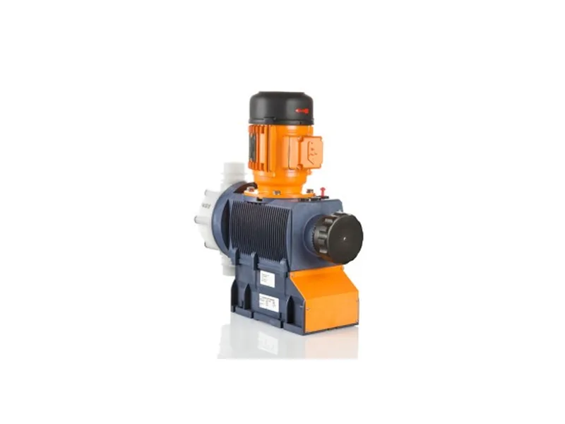
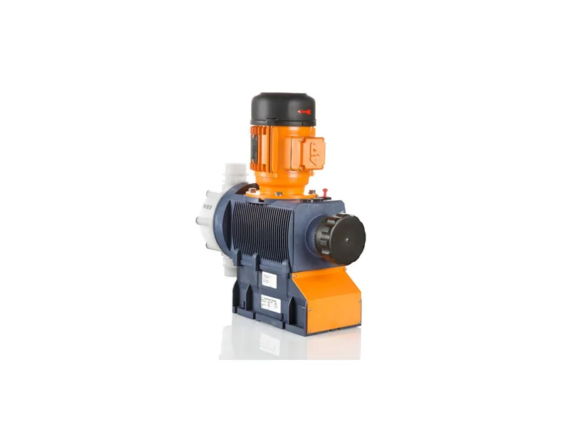
Figure 1: ProMinent Sigma/ 3 basic type motor-driven metering pump. Image source: ProMinent official website
- Coagulant: PAC or an iron salt in the inlet pipe or rapid mix tank, with fast, thorough mixing.
- pH adjustment: caustic or acid before or after the coagulant when alkalinity is short or pH is off target.
- Polymer: near the draft tube inlet in the flocculation zone, entering together with recirculated sludge.
- Phosphorus polishing: in tertiary wastewater duty, the phosphorus removal chemical usually goes in with the coagulant.
Principles for choosing the coagulant injection point are covered in coagulant dosing point selection, and the spacing between PAC and polymer in PAC and PAM dosing sequence.
Polymer and sludge recirculation
Polymer in a high rate clarifier binds the coagulated fines to the recirculated sludge. The returned solids act like seeds; floc grows around them, which is why it ends up dense and fast-settling. Too little recirculation and the floc never grows; too much and the solids concentration in the reactor rises, polymer demand climbs and the mixer works harder.
Plants normally start from the design recirculation rate and fine-tune from the solids concentration in the flocculation zone. The sludge blanket in the settling zone should stay steady: too high and sludge rolls over the plates, too low and the recycled sludge is too thin. A sludge blanket meter linked to wasting helps here, as described in sludge blanket level meters.
Watch the reactor. Good floc looks like distinct, heavy granules that drop fast when a sample settles in a beaker. Hazy water between the granules means the coagulant is short.
Tune polymer dose and recirculation together. Adjusting only one of them usually fixes one symptom and creates another.
Controlling the dose
Where flow and turbidity change a lot, pace the chemicals:
- Coagulant in proportion to inlet flow, with a turbidity or phosphorus trim where water quality swings.
- Polymer in proportion to inlet flow, at a ratio set by jar tests and floc appearance on site.
- During storms or algae blooms, check ratios manually and rerun jar tests if needed.
Residence time in a high rate clarifier is short, so dose changes show up in the effluent within tens of minutes. That makes tuning quicker than in a conventional clarifier, but it also means a dosing interruption shows up just as fast.
Pump selection
High rate clarifier installations usually treat substantial flows, so coagulant demand is high and continuous. Motor-driven diaphragm metering pumps with flow-paced control are the usual fit; the ProMinent Sigma/ 3 basic type is one larger-capacity example, described on the ProMinent Sigma/ 3 page. Polymer solution is viscous, so choose a slow stroke rate, large valves and a short, generous suction line.
Use PVC or PVDF heads for PAC and iron salts, with PVDF preferred for the more aggressive iron products. Provide a duty and standby pump for each chemical. More models are listed in the mechanical diaphragm pump category.
Common problems
What operators see most often in a high rate clarifier:
- Fine floc and carryover above the plates: not enough coagulant, poor mixing, polymer in the wrong place, or recirculation too low.
- Effluent turning cloudy: sludge blanket too high and rolling over, or a sudden flow increase that the dosing did not follow.
- Flocculator overload: recirculation too high or wasting too slow, so solids build up.
- Blocked polymer lines: poor make-down or lines left unflushed after a stop.
Before cleaning the reactor or opening a dosing pump, stop the mixer and pump and relieve pressure. PAC and iron solutions are corrosive, so wear gloves and eye protection.
Conclusion
Treat coagulant, polymer and recirculated sludge as one system. Mix coagulant fast in the rapid mix zone, apply polymer with the returned sludge in the flocculation zone, keep the sludge blanket and recirculation steady, and pace dosing to flow and turbidity. Use motor-driven diaphragm pumps with standby, and large-valve heads for polymer. Send your flow, raw water quality and existing equipment through the contact page and we will review dosing points and pumps for your high rate clarifier.
FAQ
How does dosing differ from a conventional clarifier?
A high rate clarifier adds sludge recirculation, so polymer works with the returned sludge and the two must be tuned together, with stricter demands on floc quality.
Where should polymer go?
Usually near the draft tube inlet in the flocculation zone, entering with the recirculated sludge so floc grows around it.
What recirculation rate is right?
Start from the design value and adjust from reactor solids and effluent quality; projects vary widely.
What if effluent turbidity suddenly rises?
Check sludge blanket level and inflow, then confirm the dosing pumps are running, then review the dose and rerun jar tests if needed.
Do the dosing pumps need standby units?
Yes, duty and standby is recommended. Residence time is short, so a dosing outage can push effluent out of spec quickly.