
Corrosion Inhibitor Injection for Pipelines: Points, Pumps, Control
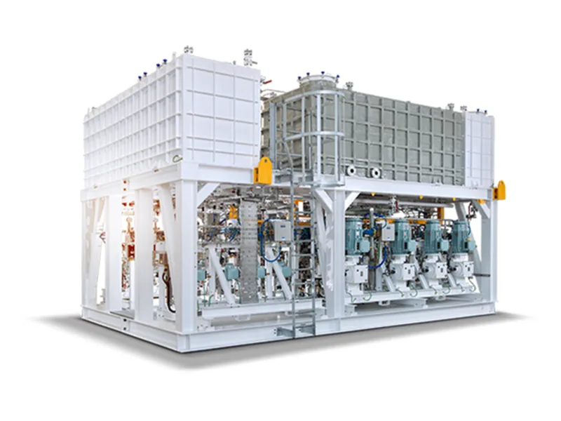
Corrosion inhibitor injection keeps a protective film on the inside of a steel pipeline, shielding it from water, CO₂ and H₂S. On long transmission lines the usual approach is continuous low-rate injection at the inlet or an intermediate station, backed by batch treatment with pigs when needed. This guide covers continuous versus batch treatment, injection points and quills, pump selection, dose control from corrosion monitoring and unmanned station setup. It is written for pipeline operations engineers and station designers.
Continuous vs batch corrosion inhibitor injection
Batch treatment pushes a slug of inhibitor between two pigs through the whole line, coating the wall in one pass. The film forms quickly but wears thinner as product flows over it. Continuous corrosion inhibitor injection adds a small, steady flow to the product and keeps repairing the film.
They work together rather than competing. A common pattern is a batch treatment at commissioning or after pigging to lay down the film, continuous chemical injection for pipelines to maintain it day to day, and another batch when monitoring trends worsen. Inhibitor chemistry (oil-soluble, water-soluble or water-dispersible) depends on the product and should be chosen by the chemical supplier from fluid analysis. This article covers the injection side only.
Choosing the corrosion inhibitor injection point
Inject upstream of the sections at risk. Typical locations are:
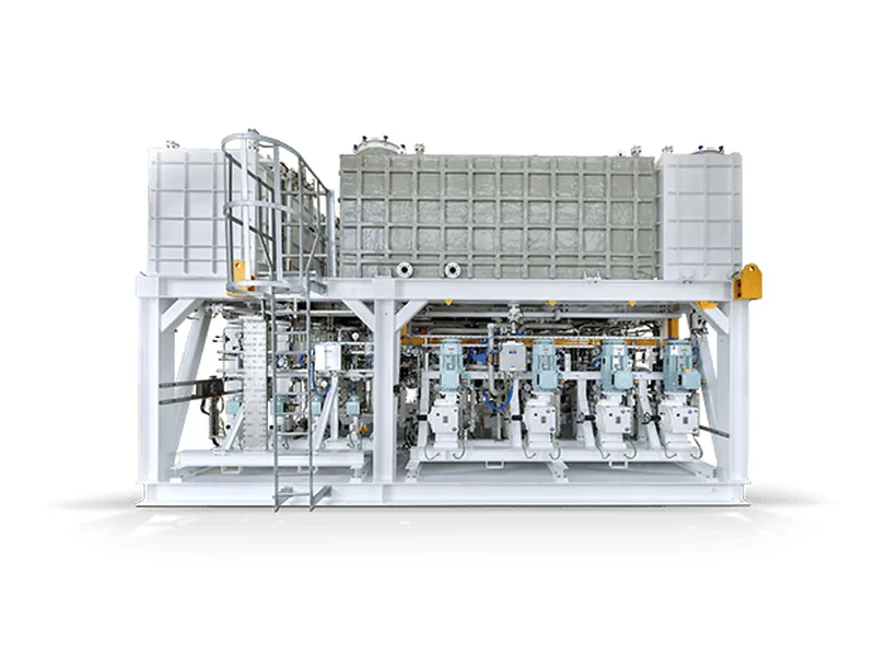
Figure 1: LEWA Chemical Injection Package front view. Image source: LEWA official website
- Inlet station or compressor discharge, so the chemical travels the full length.
- Downstream of separators and dehydration, where free water is reduced and dose is easier to control.
- Near pig launchers and receivers, to coordinate with batch treatment.
Avoid injecting upstream of equipment that will strip the chemical out; ahead of a separator, much of it may leave with the liquid phase. In gas lines, liquids collect in low spots, and that is usually where corrosion shows up.
Injection quills and atomizing nozzles
Inhibitor should not simply dribble in along the pipe wall. Fit an injection fitting with a quill that places the outlet near the pipe centerline, and use an atomizing nozzle in gas service so the chemical disperses into the stream. Put a check valve and isolation valve ahead of the quill so line product cannot back up into the injection tubing. For the role of check and injection valves, see dosing pump injection valve.
Sizing a pipeline corrosion inhibitor injection pump
Corrosion inhibitor injection on a pipeline means high pressure, low flow and long unattended run times. Size around those:
- Pressure. Rated pressure must exceed the maximum operating pressure of the pipeline, plus tubing losses and a margin.
- Flow. Calculate from the design concentration and maximum throughput, and aim to run mid-range with turndown both ways.
- Pump type. Plunger or hydraulic diaphragm metering pumps suit high pressure, low flow duty. Many inhibitors are amine-based and attack packing over time; a hydraulic diaphragm pump has no dynamic seal leaking to atmosphere, which suits unmanned sites.
- Cold weather. Inhibitor viscosity rises in winter, so heat trace and insulate the tank and lines and use a generous suction line.
Fit a relief valve, pulsation dampener and back pressure valve on the discharge, with relief set from the design pressure of pump and tubing. LEWA builds chemical injection packages for oil and gas; according to the manufacturer, drives can be electric (including solar), compressed air, gas or diesel, with pumps to API 675 or API 674. See hydraulic diaphragm metering pumps and the LEWA ecoflow.
Adjusting dose with coupons and probes
The corrosion inhibitor injection rate is not set once and forgotten. Operators install corrosion coupons and electrical resistance or linear polarization probes downstream and in low spots. Coupons are weighed periodically to calculate corrosion rate; probes give an online trend.
If corrosion rate stays high, first check the corrosion inhibitor injection system for interrupted feed, a plugged quill or degraded chemical before raising the dose. If it stays very low for a long time, review a reduction with the chemical supplier. Instrument selection and dosing integration are covered in online corrosion monitoring, so they are not repeated here.
Corrosion inhibitor injection at unmanned stations
Many block valve and intermediate stations have nobody on site, so the corrosion inhibitor injection skid must run itself and report problems:
- Power and drive. Without grid power, consider solar or pneumatic drives.
- Tank level. Remote level with low-level alarm, so the tank never runs dry.
- Flow verification. A small flowmeter or calibration column on the discharge proves chemical is reaching the line, not just that the motor is turning.
- Telemetry. Send run status, faults, level and discharge pressure to SCADA, and alarm on loss of communication.
For data acquisition and comms-loss handling, see remote monitoring for dosing systems.
Before servicing a pump or quill, close the isolation valves, bleed off pressure and confirm the line is dead. Most inhibitors are flammable organics, so electrical equipment must match the hazardous area classification, and crews should wear chemical gloves and eye protection.
Conclusion
Corrosion inhibitor injection on transmission pipelines relies on continuous low-rate feed to maintain the film, with batch treatment at startup, after pigging or when monitoring worsens. Inject upstream of risk sections and downstream of separation, use a quill to reach the centerline and atomize in gas service. Size the pump to maximum line pressure and throughput, favoring plunger or hydraulic diaphragm designs. Adjust dose from coupon and probe data, and give unmanned stations level, flow verification and telemetry. Send line pressure, throughput, product and site conditions, and contact our engineers to design the injection package.
FAQ
Can we rely on only continuous or only batch corrosion inhibitor injection?
You can, but results differ. Batch alone lets the film thin over time; continuous alone builds film slowly on new pipe. Most transmission lines combine both.
Does the quill really need to reach the pipe center?
Near the centerline is the usual recommendation, so chemical enters the main flow. Wall injection tends to run along the bottom of the pipe.
How is pump pressure set?
Above the maximum operating pressure of the line, plus tubing losses and margin. Set the relief valve from the equipment design pressure.
Inhibitor will not pump in winter. What now?
It is usually viscosity. Heat trace and insulate the tank and suction line, enlarge the suction line and ask the supplier about a low-temperature grade.
How do we prove chemical is reaching the line at an unmanned site?
Use discharge flowmeter or calibration column data and cross-check against tank level drop. A run signal alone only proves the motor is on.