
Temperature Transmitter Selection: RTD vs Thermocouple and PT100 Wiring
For most process temperatures up to a few hundred degrees, the practical answer is a PT100 RTD feeding a temperature transmitter. Move to a thermocouple when the temperature goes beyond what an RTD handles or when you need a very fast, very thin probe. Wire the RTD 3-wire as a minimum, or 4-wire for long runs and tight accuracy, pick a head-mounted or DIN rail temperature transmitter based on where the point sits, and set a span that matches the real process instead of the full sensor range. This guide is written for engineers and instrument techs specifying temperature points in water treatment, chemical dosing rooms, boiler houses and similar plants.
RTD vs thermocouple selection
An RTD (resistance temperature detector) measures temperature through the change in a metal's resistance. The PT100 is the standard: a platinum element that reads 100 Ω at 0 ℃. It is stable, close to linear and accurate in the low and middle range, which is why water, chemical and HVAC plants use it almost everywhere.
A thermocouple produces a small voltage at the junction of two different metals. It reaches far higher temperatures, can be made very thin, and responds quickly. The downsides are a millivolt-level signal, the need for cold junction compensation, and usually lower accuracy than a PT100 at moderate temperatures.
So the decision for the sensor ahead of the temperature transmitter runs like this:
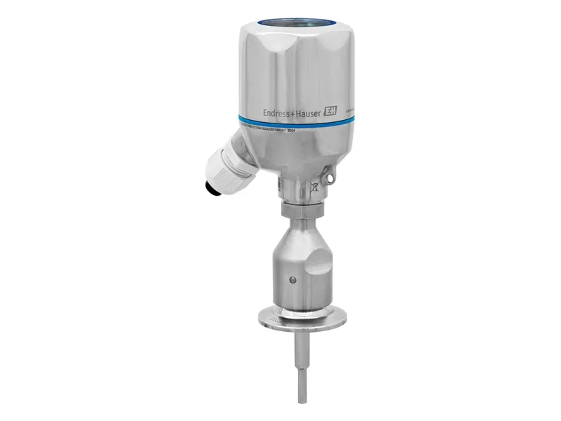
Figure 1: Endress+Hauser iTHERM TM411 RTD thermometer. Image source: Endress+Hauser official website
- Inside the RTD's working range? Use a PT100.
- Furnace, flue gas or anything beyond RTD limits? Use a thermocouple.
- Small pipe or a point that needs a very fast response? Look at thin thermocouples or fast-response RTD inserts.
Chemical solution temperature, heat tracing loops and make-up water are all comfortably PT100 territory.
PT100 temperature transmitter wiring: 2, 3 or 4 wire
An RTD signal is just resistance, and the lead wires between sensor and temperature transmitter add resistance of their own. Whatever the leads add gets read as extra temperature.
- 2-wire: all lead resistance ends up in the reading. Acceptable only for short runs with loose accuracy needs.
- 3-wire: a third conductor lets the temperature transmitter cancel lead resistance, provided all three conductors match in material, length and size. This is the industrial default.
- 4-wire: two conductors carry current and two measure voltage, so lead resistance drops out almost entirely. Use it for high accuracy or calibration work.
The mistakes we see most on site: two of the three conductors twisted together at the head, which defeats compensation, or a cable changed to a different size halfway along. Corroded or loose terminals add contact resistance and make the reading wander in a way that looks like a bad sensor but is not.
Head-mounted vs DIN rail temperature transmitter
A temperature transmitter converts RTD resistance or thermocouple millivolts into a stable 4–20 mA or digital signal for the PLC.
A head-mounted unit sits inside the sensor's connection head, so the signal becomes current right at the measuring point. That gives good noise immunity over long runs. A DIN rail unit sits in the control panel; the sensor signal travels to the panel first, which makes maintenance easier when points are close to the cabinet. A field transmitter has its own housing and often a display for harsh areas or local reading.
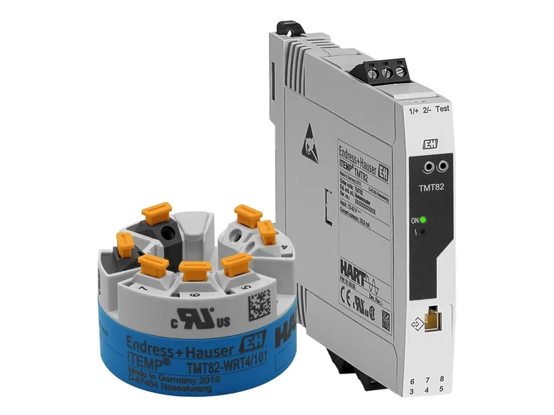
The Endress+Hauser iTEMP TMT82 is a good reference point. Endress+Hauser describes it as a two-channel temperature transmitter that accepts RTDs and thermocouples, with HART communication and head, field and DIN rail versions. Two channels let you connect two sensors for redundancy, so a failed element does not take the loop down.
Setting the span correctly
The 4–20 mA output covers whatever span you configure, and a wider span means each milliamp stands for more degrees, so resolution suffers.
- Cover normal operation plus realistic upsets, with modest margin.
- Configure the PLC with exactly the same span as the temperature transmitter, so both ends of the scale agree.
- Check which way the temperature transmitter drives on sensor break, upscale or downscale, and write the interlock logic to match.
- If the loop feeds a controller that heats or cools, confirm the temperature transmitter damping is not so slow that it hides real changes.
A heated chemical tank that only swings a few tens of degrees does not need a span covering the sensor's full range.
Thermowell insertion length
Sensors wired to a temperature transmitter rarely go straight into the process. A thermowell protects the element and lets you pull it out without draining the line, which matters on pressurized pipes and corrosive chemicals. Match the well material to the fluid; plain stainless is a poor choice for aggressive chemicals.
Short insertion is a classic cause of bad readings. If the tip only sits near the pipe wall, it reads a blend of fluid and ambient temperature. Aim to put the sensing element in the central zone of the flow; on small pipes, install at an angle or in an elbow facing the flow. A thermowell also slows response, which counts where temperature changes quickly.
Isolate power before wiring, and on pressurized lines confirm the thermowell is intact before removing the insert. Never loosen the well itself with the line under pressure. For heat tracing control on chemical lines, see dosing system insulation and heat tracing, and for compensation on analyzers, see conductivity temperature compensation.
Conclusion
A good temperature transmitter loop starts with the sensor: PT100 or thermocouple by temperature range, 3-wire or 4-wire by cable length and accuracy. Location decides head-mounted or DIN rail mounting. A span that fits the process, the right thermowell and enough insertion length complete the job. You can browse sensors and transmitters in our temperature instruments range. Send the temperature range, fluid, pipe size and signal requirement, and contact our engineers for a recommendation.
FAQ
My PT100 reads a few degrees high. Is it faulty?
Not necessarily. A 2-wire run or a miswired 3-wire circuit reads high, and so do corroded terminals. Rule those out before you measure the sensor's resistance directly.
Can one temperature transmitter accept both RTDs and thermocouples?
Many universal models can; you select the sensor type in the configuration. With thermocouples, make sure the type letter is set correctly.
Can a head-mounted transmitter sit on a hot line?
Heat in the connection head shortens transmitter life. On hot points use an extension neck, or move the electronics to a DIN rail unit.
Do the three wires in a 3-wire circuit really need equal length?
Yes. Compensation assumes equal lead resistance, so run all three in one cable with no splices to a different size.
Why does the temperature transmitter signal jump around?
Typical causes are loose terminals, signal cable run alongside power cable, a poorly grounded shield, or a sensor inserted too shallow. Work through them one by one.