
Metering Pump Assembly: Pump Head, Check Valves and Fittings in Order
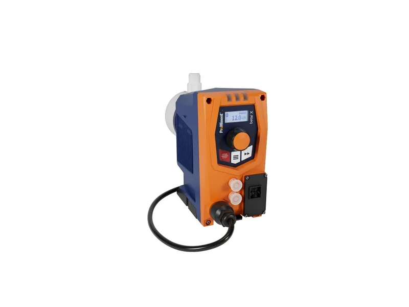
Metering pump assembly follows one simple direction: inside out, with the pump before the piping. Fit the diaphragm, close the pump head, install the suction and discharge valves, then connect tubing, the back pressure valve and the injection valve, and finish with a water test. Get the order right and most leaks, no-flow complaints and erratic output simply do not happen. This guide is written for maintenance crews and installers, using the ProMinent beta/X solenoid diaphragm pump as the reference. The liquid end of a motor-driven diaphragm pump follows the same logic, but take torque values and details from your own manual.
The order at a glance, with each step covered below:
- Clean parts and inspect or replace seals.
- Fit the diaphragm at the stroke position the manual specifies.
- Close the head with cross-pattern bolt tightening in stages.
- Fit the suction and discharge valves, inlet low and outlet high.
- Connect tubing, back pressure valve and injection valve.
- Water test, then reconnect to chemical.
Before You Start: Preparing Parts for Metering Pump Assembly
Do not put parts straight back in. Rinse crystals and debris off balls, seats and the diaphragm faces with clean water. If the pump handled a corrosive chemical, neutralize and flush it before anything else, and wear gloves and eye protection.
O-rings and gaskets should usually be replaced, especially ones that are flattened or have been reused before. Lay parts out on a clean bench in the order you removed them, and keep the suction valve set apart from the discharge valve set. Mixing the two is a very common reason a freshly rebuilt pump will not deliver.
Check materials too, because metering pump assembly with the wrong parts fails early. On the beta/X, the PVT version has a PVDF head and PVDF seats with aluminum oxide ceramic balls, while the SST version has a 1.4404 stainless head with zirconium oxide ceramic seats. Replacement parts should match the original material code, not whatever is on the shelf.
How to Assemble a Dosing Pump Head: Diaphragm and Stroke Position
In metering pump assembly the diaphragm goes on first. Check which side faces the drive; it is usually marked. On solenoid and motor-driven diaphragm pumps alike, stroke position matters at this point: many manuals ask you to set the stroke knob to a specified position while fitting the diaphragm so it seats correctly. Requirements differ by brand, so follow the manual rather than habit.
Once it is screwed home, look at it from the front. The clamping edge should be even all round. An off-center diaphragm gets pinched when the head bolts go down and will leak early. If the head will not seat after a diaphragm change, our article on a pump head that won't close after diaphragm replacement covers the usual causes.
Closing the Head: Cross-Pattern Bolt Tightening
Locate the head on its spigot and make sure the ports face the right way, inlet at the bottom and outlet at the top. Tighten the bolts in a cross pattern over two or three passes: finger tight to start, then more torque on each pass. Do not run one bolt fully tight before the others. A head pulled down on one side seals badly, and a plastic head can crack.
Use the manual's torque value and go gently on plastic heads. Re-check the bolts after the pump has run for a while; this step is often skipped during metering pump assembly.
Check Valve Orientation: The Step Most Often Done Wrong
Valves cause more metering pump assembly errors than anything else. Remember one rule: liquid only travels upward through the head. The suction valve sits below the head and the discharge valve above it, and the flow arrows on both point up, in the direction of flow.
Inside each valve, seats, balls, guides and O-rings must go back in their original stack. The ball should drop freely onto its seat, and the sealing faces should be free of scratches. On double-ball valves, keep both ball-and-seat pairs in order. For what happens when a valve goes in backward, read metering pump check valve direction.
Tubing, Back Pressure Valve and Injection Valve Installation
In a correct metering pump assembly, connect the lines only after the valves are in. Cut tubing square, push it fully onto the insert, then tighten the union nut. On threaded fittings, keep thread tape out of the bore, because loose fragments are a classic cause of a ball that will not seat.
Typical discharge-side accessories:
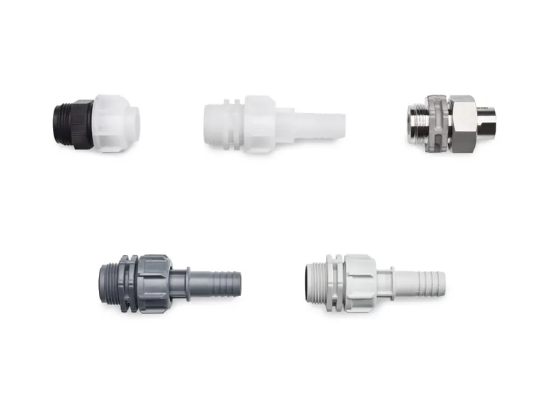
Figure 1: ProMinent injection valves for low-pressure metering pumps. Image source: ProMinent official website
- Relief valve, to protect against a closed valve downstream.
- Back pressure valve, to steady discharge pressure and stop siphoning.
- Isolation valve, for maintenance.
- Injection valve, at the injection point, fitted last.
ProMinent's low-pressure injection valve uses a spring-loaded ball check with a Hastelloy C spring and an opening pressure of about 0.5 bar, and it can be fitted in any position. The TT version without a spring is meant only for vertical installation from below. ProMinent also points out that an injection valve should not be treated as a leak-tight shut-off device, so keep an isolation valve in the line for maintenance. See what an injection valve does and our dosing accessories range for the parts.
Water Test and Common Metering Pump Assembly Mistakes
Finish every metering pump assembly with a run on clean water. Bleed the head and confirm steady delivery at the outlet. Then check the head joint, both valves and every fitting for weeping. Only then reconnect to chemical.
Three faults account for most rework: suction and discharge valves swapped, so the pump clicks but nothing comes out; head bolts tightened one side at a time, so the joint weeps; and tape or old seal fragments in the valve chamber, so flow swings up and down. All three typically happen when the metering pump assembly order is broken, for example plumbing the lines before the valves are finished.
Conclusion
A sound metering pump assembly runs in this order: clean and inspect parts, fit the diaphragm at the correct stroke position, close the head with cross-pattern bolts in stages, fit the valves inlet low and outlet high, connect tubing, back pressure and injection valves, then water test. Each step of metering pump assembly has its own way to go wrong, and following the sequence is faster than fixing leaks later. For more pump types and accessories, see the ProMinent brand page. If you are unsure about a part number, send the pump model and material code to contact our engineers.
FAQ
Can I reuse O-rings during metering pump assembly?
It is not recommended. Old O-rings are usually flattened or hardened by chemicals and tend to weep. New ones cost little.
The suction and discharge valves look the same. How do I tell them apart?
Use the flow arrow and the position: the arrow points with the flow, suction valve below, discharge valve above. Mark them when you take the pump apart.
The pump will not deliver after reassembly. What do I check first?
Look at valve orientation and for a stuck ball, next for air trapped in the head, and last for air leaks on the suction line.
How tight should the head bolts be?
Follow the manual torque. Without a torque wrench, tighten in a cross pattern in stages until the joint is evenly seated, and re-check after running.
Where exactly does the injection valve go?
At the point where the chemical enters the main line. A spring-loaded valve can go in any position; one without a spring must be installed vertically from below.