
Dosing System Design Problems: What Breaks Between Drawing and Site
A dosing skid can look complete on paper and still fail to prime, shake the pipework, or leave no place to drain a flush once it reaches the plant. That is usually not a wrong pump model. It is dosing system design that did not freeze the installation conditions. This article is for people who produce construction drawings and who commission the skid. It stays on the gaps between the drawing and the room, and it does not repeat process calculations for a single chemical. Phosphorus-removal process choices are covered in phosphorus removal dosing system.
Suction lift and priming are often only a note in dosing system design
How high a metering pump can lift depends on the lowest liquid level, suction pipe length, diameter, viscosity and temperature. A drawing that just says "self-priming" or gives a single mounting height will not survive a pump placed on a platform with a suction line that walks around a column. Dosing system design should put the geometric lift from low level to the pump inlet, the pipe length and the elbow count into the duty table, and it should say whether the pump is flooded.
Priming (the head and suction line must be full of liquid before the first start) is often missing from the drawing. A high tank that floods the inlet is easy. When the level sits below the pump, a suction line with no priming port or foot valve will spend a long time on air, or never pick up at all. Place a priming connection near the pump inlet and write the first-fill and later venting steps in the notes, instead of improvising with a temporary hose on site.
Pipe size, accessory space and supports drift off the calculation
Running the discharge at the pump connection size looks neat, but pulsation and friction may be higher than assumed. Dosing system design should step up to the calculated diameter soon after the pump, and it should leave length and service access for the pulsation damper, back-pressure valve, relief valve and calibration column. If those parts are packed into one cluster, later valve service and flow checks get in each other's way. What each accessory does is summarized under dosing accessories; the drawing does not need to re-explain the principles.
Supports and flexible joints are often left as "decide on site". A rigid discharge line clamped to a steel beam will carry the pump's reciprocating motion into valves and instruments. A suction loop that traps a pocket of air will make the ball chatter and the flow wander. The drawing should show slope, high-point vents and support spacing, not just a straight diagrammatic line.
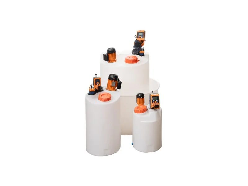
ProMinent DULCODOS eco packages arrange the pump, back-pressure valve and pipework as a module. The site still has to redraw foundation height, suction length and flush connections around the real tank farm. A catalogue layout is not a construction drawing.
Flush, drain and calibration belong in the design basis
Lines have to be flushed when you change chemical or take a pump out of service, yet dosing system design often omits a flush-water connection and a place for the waste to go. Acid and hypochlorite must not meet in the same pipe. The flush sequence and the drain point have to be visible on the drawing. Operating detail is in dosing line flushing; the design stage at least has to leave the connections and the slope.
If the calibration column exists only on the bill of materials, the commissioning team will add a temporary clear tube that is hard to read and easy to knock. Draw the column at the pump discharge, before the back-pressure valve or wherever the maker specifies, and make sure an operator can stand there and see the level.
A drawing review can be three questions: will the pump still prime at low level, is there room to remove each accessory, and where do flush water and waste go. If any answer is missing, do not release the skid for fabrication. Package layouts on the ProMinent brand page can be used as a starting point, then redrawn for the tank farm you actually have.
On site, one more detail is easy to miss. After the suction line passes through a platform or a wall, extra unions can leak air and make the pump look faulty. Dosing system design should show how many unions are allowed and where they sit. Use as few as you can, and put the ones you must have where a leak test is easy.
A short drawing review list
Before a dosing system design is released, a short list usually catches the gaps that show up on site:
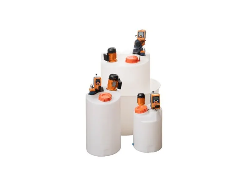
Figure 1: ProMinent DULCODOS eco. Image source: ProMinent official website
- Geometric lift from low level to the pump inlet, suction length and elbow count, written into the duty table
- A pipe-size transition from the pump connection to the calculated diameter, with space for the damper and back-pressure valve on PE or PVC pipe
- A priming port, high-point vents, and a visible route for flush water and waste
- A calibration column at the discharge, before the back-pressure valve or where the maker specifies
Pipe material generally depends on the chemical and the temperature; PE, PVC or a PTFE-lined option are common starting points. These items look minor on paper, and they are the ones most often left for the installers to invent.
Conclusion
What breaks in dosing system design is rarely "one pump left off the drawing". It is suction and priming conditions that were never written down, pipe and accessory layout copied from the pump connection, and flush or calibration left for the commissioning week. Put low level, pipe length, accessory spacing and flush connections into the design basis so the installation still matches the calculation. If the dosing system design still has open items, send the chemical, the flow, the tank layout and the mounting height, and contact our engineers to check whether those items are missing from the drawing.
FAQ
The pump curve lists a suction lift. Do I still have to calculate it?
Yes. Catalogue values are measured at a stated diameter, viscosity and level. If dosing system design lengthens the suction line, adds elbows or lowers the liquid level, the real lift can exceed the catalogue figure and must be recalculated for the site.
Can the discharge stay at the same size as the pump connection?
Not always. The connection is only the pump end. The pipeline still has to be sized for velocity, pulsation and accessory fittings. Many dosing system design packages typically enlarge the line one size just after the pump, then mount the damper and back-pressure valve.
Can we start up without a flush connection and add it later?
You can start temporarily, but changing chemical or taking the line out of service will make a thorough flush difficult, and leftover chemical is more likely to mix. If dosing system design can leave a flush point and a drain now, do not defer it to a later modification.
Does every pump need its own calibration column?
Continuous duty that is judged on flow should have one. Several small pumps can share a column, but the change-over valves and the operating note have to be clear so two pumps are not discharged into the same column at once.
Can a manufacturer's package layout be used as the construction drawing?
Not as-is. Package drawings are modular. Tank height, suction length and the flush destination have to follow the site, and dosing system design should issue a revised drawing before construction starts.