
Metering Pump P&ID Symbol: Pump, Accessories and Tag Numbers
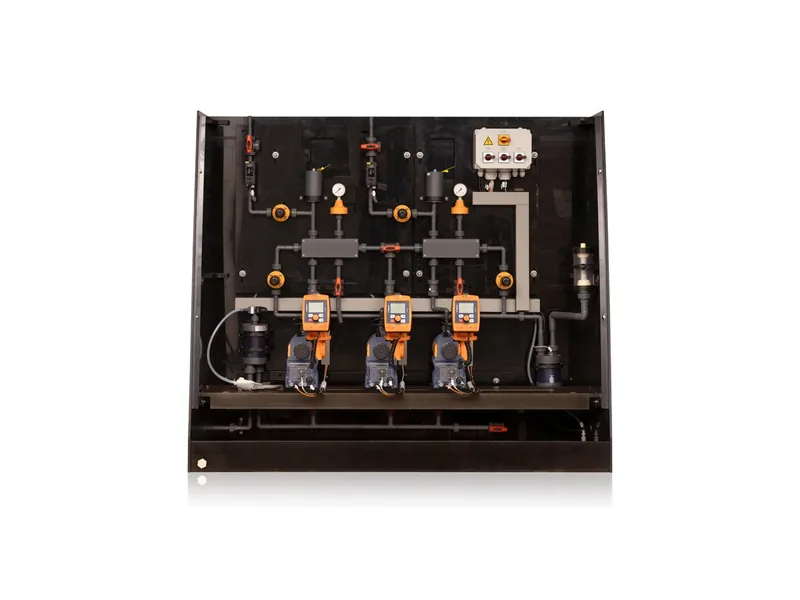
A metering pump P&ID symbol is usually drawn as the standard pump circle with a diagonal arrow through it to show adjustable capacity, although some engineering firms use the reciprocating pump symbol with a note instead. Instrument tags generally follow ISA 5.1 lettering, and equipment symbols follow ISO 10628 or the client's own legend sheet. This article is about drawing the pump, its accessories and tags, not about reading a finished diagram.
Common ways to draw a metering pump P&ID symbol
You will see three conventions on real drawings:
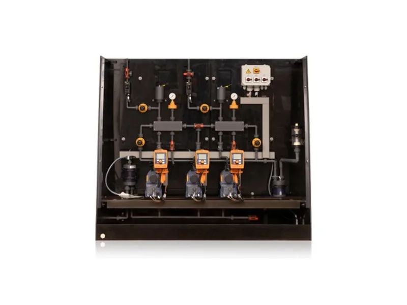
Figure 1: ProMinent DULCODOS panel DSWC backplate assembly. Image source: ProMinent official website
- Pump circle with a variable arrow. The circle is the pump and a diagonal arrow marks adjustable flow. Many skid builders use this.
- Reciprocating pump symbol. The diaphragm or piston pump shape from the standard, with "metering pump" written beside it.
- Custom legend entry. The engineering firm defines its own metering pump P&ID symbol on the legend sheet and uses it across the job.
Any of these is acceptable. What matters is that the whole drawing set uses one convention and the legend defines it. The classic review comment is a process P&ID using one symbol while the skid vendor's drawing uses another, and nobody can match them on site.
What to show beside the metering pump P&ID symbol
The metering pump P&ID symbol alone does not say enough. Put this information next to it or in the equipment list:
- Pump type, such as hydraulic diaphragm, mechanical diaphragm or solenoid, referenced through the tag.
- Drive and adjustment. A VFD is usually shown with an SC tag at the motor, and an electric stroke actuator with an actuator symbol on the pump.
- Duty and standby units drawn separately and tagged A and B, for example P-101A/B.
- Materials of the liquid end where the chemical needs it, for example PVDF or 316 SS, normally in the equipment list.
The goal of a complete metering pump P&ID symbol is simple: someone reading the P&ID should know whether the pump can be adjusted, and how, without opening the datasheet.
Accessories people forget to draw
On chemical feed drawings the accessories get missed more often than the pump. On the discharge side you normally need:
Pressure relief valve. Shown between the pump outlet and the first isolation valve, with the set pressure beside it or in the instrument index. If the pump has an internal relief valve, note that on the drawing so the reviewer does not ask for a second one.
Back pressure valve. Required when discharge pressure is lower than suction pressure or when injecting into a vacuum. Draw it with the pressure-regulating valve symbol and label it BPV.
Pulsation dampener. A small vessel close to the pump outlet, typically fitted on long lines or when there is a flow meter downstream.
On the suction side, show the Y-strainer, isolation valve and calibration column, drawn as a graduated standpipe above the suction line. Our metering pump installation diagram shows where each item usually sits.
Instrument tags and signal lines
ISA 5.1 lettering is the most widely understood. Typical tags on a dosing system:
- FT/FIC: dosing flow transmitter and flow control. Some projects use a calibration column instead of an inline meter.
- LSL/LSLL: tank low and low-low level switches tied to the pump trip.
- PI/PSH: discharge pressure gauge and high pressure switch to catch a blocked line.
- SC/ZC: speed control and stroke position control when the pump is driven by a remote 4-20 mA signal.
Electrical signals are usually dashed lines and pneumatic signals use the hatched line. Write interlocks next to the devices, for example "LSLL-101 trips P-101A/B". For a worked layout, see our sodium hypochlorite dosing flow diagram.
Drawing mistakes we see most
One is drawing a plain centrifugal pump instead of a metering pump P&ID symbol, with no adjustment mark. The contractor pipes it like a centrifugal pump and leaves out the relief valve. Another is putting the back pressure valve upstream of the relief valve, so commissioning never reaches the right pressure. A third is two duty and standby pumps sharing one suction branch with a single isolation valve, which makes maintenance impossible without stopping both.
Pre-issue checklist
Before the drawings go out, check:
- The metering pump P&ID symbol is defined on the legend and used consistently.
- Every pump outlet has a relief valve or a note about the internal one.
- A back pressure valve is shown wherever suction pressure can exceed discharge pressure.
- Tank level switch tags match the interlock notes.
- Duty and standby pumps have their own valves and tags.
For packaged skids, ask the vendor for a tagged P&ID and have the engineer insert it into the master set. Taking the ProMinent DULCODOS panel DSWC as an example, pump, valves and instruments are mounted on one backplate, and the vendor drawing typically shows every accessory. You can review options on our dosing skid page, see the ProMinent brand page, and read how to read a dosing system flow diagram.
Conclusion
There is no single correct metering pump P&ID symbol. The pump circle with a variable arrow is the most common, and the real requirement is a clear legend used across the whole set. Relief valves, back pressure valves, dampeners and calibration columns are the items most often left off, and ISA 5.1 tags with written interlocks make the drawing usable on site. If you need a tagged P&ID for a dosing skid or a second check on your drawings, contact our engineers.
FAQ
Is there a standard metering pump P&ID symbol?
There are reference standards such as ISO 10628, but most firms define their own on the legend sheet. Generally the project legend wins.
How do you tell a metering pump from a centrifugal pump on a P&ID?
The metering pump P&ID symbol usually carries a variable arrow or uses the reciprocating pump shape. The equipment list should confirm the pump type.
Do I draw an internal relief valve?
It is a good idea to draw it next to the metering pump P&ID symbol or add a note. That tells reviewers and commissioning staff the outlet already has overpressure protection.
Should a metering pump be tagged P or something else?
Most projects tag the metering pump P&ID symbol with P, while some use DP for dosing pumps. Follow the project numbering procedure and keep it consistent.
The skid vendor's drawing does not match ours. What now?
The project legend usually takes priority. Ask the vendor to redraw to your legend and match the tags to the master P&ID.