
How to Read a Metering Pump Installation Drawing and Its Details

A metering pump installation drawing usually comes as two layers: a layout sheet that shows where everything goes, and detail sheets that zoom in on one spot and show exactly how to build it. Installers work mostly from the details, so knowing how to read them saves a lot of rework on site.
We use a ProMinent gamma/X solenoid pump with a suction assembly as the running example, since this is a very common arrangement on tank-top and wall-mounted dosing points.
Layout Sheet vs. Detail Sheet
The general metering pump installation drawing is typically a plan or isometric view. It shows tanks, pumps, valves, piping and flow direction, and answers the question "what is there and where does it connect". For that level, see our guide to the metering pump installation diagram and the dosing system flow diagram.
A detail sheet is drawn at a much larger scale, often 1:5 or 1:10. It shows one node: bolt sizes, fitting types, solvent-weld or threaded joints, distances from wall and floor. When the foreman says "build it per drawing", this is usually the sheet he means.
Four Nodes in Every Metering Pump Installation Drawing
Pump base or bracket
On a metering pump installation drawing, the base detail gives the plinth or bracket size, the position and size of anchors or expansion bolts, and whether there is a vibration pad. Solenoid pumps are small, so the detail often shows a wall bracket or a tank-top mounting with the bracket material and fixing method.
Suction node
For tank-top installation, the metering pump installation drawing shows how the suction assembly enters the tank: suction pipe length, foot valve height above the tank floor, and where the level switch sits. Pumps like gamma/X are often supplied with a suction lance carrying a float level switch, and the detail states how much clearance to leave above the tank bottom so the pump does not pick up sediment.
Discharge valve train
This node shows the order and spacing of the back pressure valve, relief valve, pulsation dampener and pressure gauge, plus the connection sizes. Check valve direction is the item most often drawn or installed backwards; compare with our note on check valve installation direction.
Injection point
The injection detail shows how the injection valve enters the main line: side or bottom tapping, insertion depth, and an isolation valve between the injector and the pipe. This node decides whether the chemical mixes evenly, so read it carefully.
Reading a Metering Pump Installation Drawing Step by Step
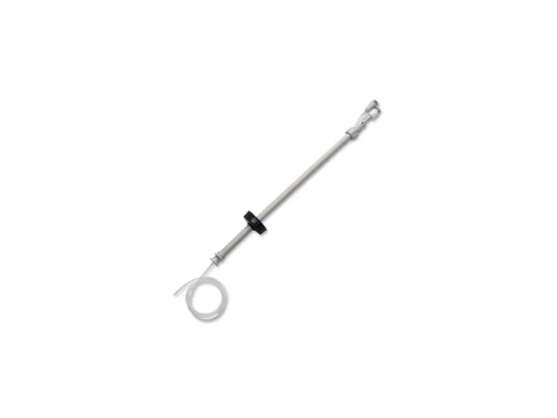
Figure 1: ProMinent gamma/X suction lance with float switch. Image source: ProMinent official website
- Start with the title block and reference number. Confirm which point on the layout this detail belongs to, so pump A's detail is not used for pump B.
- Check scale and units. Details are generally in millimetres, while elevations are sometimes in metres.
- Read the material list. Pipe, gasket and bolt materials must suit the chemical; sodium hypochlorite and plain carbon steel bolts do not mix.
- Read the notes. Slopes, support spacing and pressure test requirements usually sit in the notes corner and are easy to miss.
Checking the Metering Pump Installation Drawing on Site
A metering pump installation drawing is normally based on standard practice, and the site rarely matches it perfectly. Walk the site with the sheet in hand and check:
- the real tank height and nozzle positions against the suction pipe length on the drawing;
- the actual main line material and size, and whether the injection fitting will connect directly;
- whether cable trays or ducts already occupy the pump position, and if there is service space;
- where power and control cables will enter.
If anything differs, ask the designer before changing dimensions on site.
Common Reading Mistakes
The first is treating a schematic valve sequence as true spacing. The valves end up jammed together and no wrench fits between them. The next is ignoring elevations and mounting the pump above the tank, which turns a flooded suction into a suction lift. The third is building from an old revision of the metering pump installation drawing and finding out at handover that the injection point moved two revisions ago.
Questions to Ask at the Drawing Handover
Go to the handover meeting with questions rather than just signing the transmittal. We usually tell installers to ask:
- Is the suction assembly supplied as a kit, or made on site, and who cuts it to length?
- Does the pump supplier provide the injection valve and isolation valve, or the piping contractor?
- Who supplies the wall bracket and cuts the tank-top opening, and which sheet sets its size?
- What test pressure applies, and should the pump and valve train be isolated during the test?
These sound small, yet on site each side often assumes the other will bring the parts. Mark the answers on the metering pump installation drawing by hand, sign it and keep a copy.
Conclusion
To read a metering pump installation drawing well, focus on four nodes: base, suction, valve train and injection point. Read title, scale, materials and notes in that order, then walk the site and check each item. That approach usually gets the job right the first time. For gamma/X configuration options see our ProMinent gamma/X overview, and for similar models browse solenoid metering pumps. If you want a second pair of eyes on your metering pump installation drawing against your site conditions, contact our team.
FAQ
Who normally produces the detail drawings?
Either the design institute or the dosing equipment supplier. Supplier details match the pump more closely, while designer details match the site piping.
Can we install without a detail sheet?
Small jobs sometimes follow the pump manual alone. For injection tappings and concrete bases, a detail sheet is still recommended.
What if the drawing conflicts with the pump manual?
Confirm with both the designer and the supplier. Typically the manual governs the pump itself, and the drawing governs piping and civil work.
How do I decode the symbols on a metering pump installation drawing?
Use the legend sheet. Standard valve and instrument symbols are listed there, and project-specific symbols should be added by the designer.
Should the chemical name appear on the detail?
Yes. The chemical and its concentration drive material selection, so stating them prevents wrong parts being bought or fitted.