
Dosing System Control Settings: Level Setpoints, Interlocks, Alarms
Dosing system control settings come down to three groups of numbers in the PLC or panel: tank level setpoints, interlock conditions between equipment, and alarm thresholds with their delays. Level points decide when to refill and when to stop the pump. Interlocks decide what is allowed to run. Alarm values and delays decide whether operators trust the alarms or start ignoring them. This guide is for controls engineers, consultants and operators taking over single-tank or twin-tank dosing packages.
Tank level alarm setpoints: the four points
Level points are the first group of dosing system control settings. Most chemical tanks use four: high-high, high, low and low-low. With a continuous level transmitter they are software values. With float switches they are physical mounting heights, which means changing them later involves moving brackets. Fix them before the drawings are issued.
A sensible way to place them:
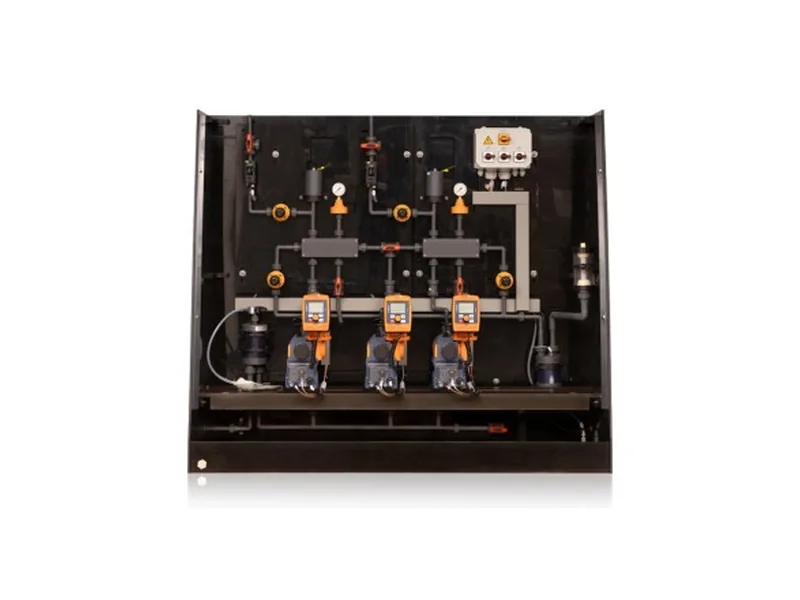
Figure 1: ProMinent DULCODOS panel pre-assembled dosing station. Image source: ProMinent official website
- Low-low: pump stop. It sits above the suction inlet with enough margin to avoid vortexing and air entry, and above any sludge layer at the tank bottom.
- Low: alarm and start refill or batching. The volume between low and low-low should last long enough for someone to respond.
- High: stop the fill. Leave room for surface movement while mixing and for volume change when powder dissolves.
- High-high: last alarm before overflow, usually interlocked to close the fill valve.
As an example, a tank might start at 95%, 90%, 20% and 10% of tank height. Treat that as a starting point and check it against tank shape, suction height and how often operators walk past.
Interlock settings in dosing system control
The second group of dosing system control settings is interlocks. Separate equipment protection from process logic. Protection interlocks should be hard: low-low level stops the pump, high discharge pressure stops the pump, mixer overload trips the mixer. Ideally these sit in the PLC and in a hardwired circuit as well. Process interlocks can be softer: switching to the standby pump on a duty fault, or stopping dosing when plant flow is zero. These can live in software with a permitted operator bypass.
Mixers are typically blocked unless the liquid is a set distance above the impeller, because running dry damages the gearbox and shaft seal. In a batching sequence, water fills to its setpoint before powder feed and mixing start, and the pump is only allowed to draw from that tank after the mixing time has elapsed.
Standby pump changeover settings
In most dosing system control settings, the duty pump fault is confirmed for a few seconds before changing over. Keep the fault logged and do not auto-return to the duty pump. For duty rotation, a daily or run-hours based cycle usually keeps wear even.
Alarm values and alarm delay settings
Alarm values are the third group of dosing system control settings. Alarms set too tight fire all day, and operators end up inhibiting them, which is worse than having none. Common dosing system control settings in this area:
- High discharge pressure alarm: above the highest process back pressure and below the relief valve set point. Our guide to relief valve set points for dosing pumps covers how that value is chosen.
- Low level alarm delay: the surface moves during mixing, so a delay of about 5 to 10 seconds cuts nuisance alarms. Keep the low-low pump stop delay short.
- Run feedback timeout: if no run signal returns within a few seconds of a start command, raise a pump fault.
- Low flow alarm: where a flow meter is fitted, pump running with near-zero flow usually means air lock or a stuck check valve.
For wiring and delay details on the switch itself, see our article on dosing pump low level alarm setup.
4–20 mA scaling and signal loss
Analog scaling is the part of dosing system control settings that people overlook. Level, flow and pressure transmitter ranges in the PLC must match the instrument nameplate. If the engineering values for 4 mA and 20 mA are wrong, every level point shifts with them. When a metering pump takes a 4–20 mA speed signal, decide what happens below 4 mA. A broken wire is generally treated as a fault and the pump stops. Our comparison of 4-20 mA and pulse control explains the signal options.
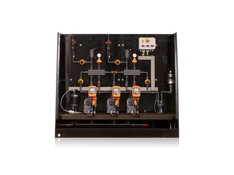
On pre-assembled panels such as the ProMinent DULCODOS panel, pumps, valves and instruments arrive mounted on one board. On site, the main job is checking that level points, alarm delays and external signal ranges match the process.
Field mistakes with dosing system control settings
The most common mistake is copying drawing values without measuring. Float switches often trip a few centimeters away from the drawing height, and a low-low point near the suction inlet lets the pump draw air. Another one is winter viscosity. Discharge pressure runs higher in cold weather, so a pressure alarm set just above the summer reading will nuisance trip in winter. Also agree with the client whether pumps restart automatically after a PLC power loss or wait for an operator. Manual confirmation is generally the safer choice.
Conclusion
Set dosing system control settings in order: level points to begin with, then protection and process interlocks, then alarm values and delays, and check analog scaling and wire-break behavior separately. Start from design values, correct them with measurements during commissioning, and record every change. Browse our controllers range or the ProMinent brand page for integrated options. To review the dosing system control settings on an existing skid, send tank size, pump model and control method and contact our engineers.
FAQ
How many level switches does a dosing tank need?
Usually three or four in typical dosing system control settings, with low-low pump stop as the minimum. With a continuous transmitter, add an independent low-low switch if you want hardwired protection.
Why add a delay to the low level alarm?
Mixing and filling make the surface move, so an undelayed switch chatters. A few seconds is enough, and protection trips should use shorter delays.
Is it acceptable to leave alarm inhibits on?
No. Use inhibits only during maintenance, remove them afterwards and note it in the shift log.
How should automatic standby changeover be configured?
Trigger it from a confirmed duty pump fault, start the standby pump and raise an alarm. Do not switch back automatically until someone has checked the duty pump.
Do I need to stop the system to change parameters?
Most dosing system control settings, such as level points and delays, can usually be changed online. Changes to interlock or safety logic are better made with pumps stopped, followed by a retest.