
Metering Pump VFD Settings: Drive Parameters for Dosing Pumps
Getting metering pump VFD settings right decides whether the pump actually follows the flow signal you send it. Plenty of skids leave the drive on factory defaults, and the pump runs fine at full speed but trips on overload at low flow, or delivers far less than the DCS asks for at a 50% signal.
This guide walks through the parameters in the order you would set them on site. It applies to motor-driven mechanical diaphragm metering pumps and plunger pumps fitted with a general-purpose drive or an integrated inverter motor.
Check Three Things Before Touching Metering Pump VFD Settings
Before you open the parameter menu, confirm the basics:
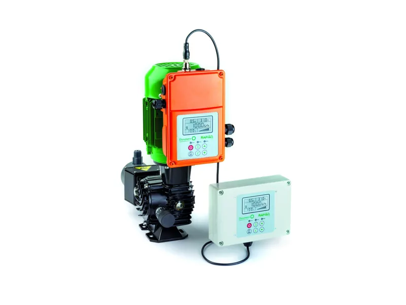
Figure 1: Doseuro RAPIDA 2.0 inverter motor on an SR series metering pump. Image source: Doseuro official website
- Is the motor inverter-rated, or does the pump maker approve speed control on the standard motor?
- How is flow split between stroke length and speed? The usual answer is a fixed manual stroke plus automatic speed, but some plants also want a stroke control actuator.
- Where does the run signal come from: 4-20 mA, hard-wired start/stop terminals, or Modbus?
The Doseuro RAPIDA 2.0 inverter motor is a useful reference point. It combines a three-phase asynchronous motor and an inverter board in one unit, fits the whole Doseuro SR series, runs on a 220 V supply, and offers manual, analog, Modbus and level control functions. It can also be retrofitted to existing pumps, and Doseuro quotes 1:500 adjustment when the inverter and the manual stroke knob are combined. With an integrated unit most metering pump VFD settings arrive matched from the factory. With a separate drive, every item below is yours to fill in.
Motor Nameplate Data Comes First
The first metering pump VFD settings to enter are rated voltage, rated current, base frequency, rated speed and pole count from the motor nameplate, not from the pump datasheet. Small dosing pump motors are usually in the 0.09 kW to 0.37 kW range with a full-load current well under 2 A.
If the drive is oversized and the motor current is left at the drive default, the electronic overload is useless. The motor can cook without a single alarm. Most drives offer an auto-tune; a static tune is usually enough because a pump with a gearbox is hard to uncouple for a rotating tune.
Maximum and Minimum Frequency in Metering Pump VFD Settings
Set maximum frequency to the motor base frequency, 50 Hz or 60 Hz depending on your supply. Running above base speed to squeeze out more flow needs the pump maker's approval. Check valves have a stroke rate limit, and above it accuracy falls apart.
Minimum frequency depends on how the motor is cooled. A shaft-mounted fan slows down with the motor, so long periods at low speed overheat it. An inverter-duty motor with a separate fan can go lower. Take the turndown from the motor and pump documentation instead of guessing. Low-speed cooling is a topic of its own; for metering pump VFD settings the point is simply that the minimum is a protection limit, not a convenience.
Ramp Times and Stop Mode
A reciprocating pump is a pulsating load. Very short acceleration causes overcurrent trips; very short deceleration can trip on DC bus overvoltage. Ramps of about 5 to 10 seconds generally work, and long discharge lines or high back pressure may justify a little more.
In most metering pump VFD settings, ramp-to-stop is a better choice than coast. If the pump is restarted while still spinning down, many drives fault unless flying start is enabled.
Use a Constant Torque V/f Curve
This is the classic mistake. Many drives ship with a variable torque curve meant for fans and centrifugal pumps. A metering pump pushes against roughly the same discharge pressure on every stroke regardless of speed, so it is a constant torque load.
On a variable torque curve the drive starves the motor of voltage at low frequency, and the pump stalls or stutters at low flow. Correct metering pump VFD settings use a linear V/f curve with a modest torque boost at the low end. Too much boost makes the motor run hotter at low speed, so increase it in small steps.
Analog Scaling and Signal Loss
Among the metering pump VFD settings, analog scaling causes the most confusion. Set the input type to current, map 4 mA to minimum frequency and 20 mA to maximum frequency. Mapping 4 mA to 0 Hz pushes the pump into the speed range where it performs worst. For wiring practice, see our notes on 4-20 mA and pulse control.
Decide in advance what happens on a broken signal wire:
- Hold the last speed, for chemicals that must not stop, such as disinfection.
- Run at a preset safe speed.
- Stop and alarm, for chemicals where overdosing is the bigger risk, such as strong oxidizers.
With Modbus control, set the communication timeout action the same way.
Protection, Fault Relay and Auto-Restart
Protection belongs in your metering pump VFD settings too: set motor thermal protection to the actual nameplate current. If the motor has a PTC thermistor, wire it to the drive's thermistor input. Route the drive fault relay to the PLC or DCS so a stopped pump raises an alarm.
Treat auto-restart after a power loss carefully. It is convenient, but if the day tank is empty or a technician has the discharge line open, an automatic start is a hazard. A common approach is to allow restart in the drive and let the PLC confirm tank level and permissives before issuing the run command. On first power-up, also confirm motor rotation direction.
Calibrate Flow After Commissioning
No set of metering pump VFD settings is finished until flow is checked. Flow is roughly proportional to frequency, but it drifts at the low end. Check actual output with a calibration column at about 20%, 50% and 100% signal, and use the measured values in the control system scaling. Repeat the check whenever stroke length changes.
Conclusion
Good metering pump VFD settings treat the pump as a constant torque reciprocating load: accurate nameplate data, frequency limits within the motor and pump ratings, sensible ramps, 4 mA mapped to minimum speed, and planned responses to signal loss and faults. A three-point calibration afterwards tells you more than any default value. If you are unsure of the allowed speed range, send us the nameplate and process data through our contact page.
FAQ
Why is flow not linear after I change metering pump VFD settings?
Low-speed slip at the check valves and weak motor torque are the usual causes. Raise the minimum frequency or open the stroke length so the drive works in its mid to upper range.
Should I change the carrier frequency?
Usually the default is fine. With long motor cables or a hot motor, a lower carrier frequency can reduce heating and interference.
Can a standard motor run on a VFD?
Short periods of moderate speed reduction are typically acceptable. Continuous low-speed duty needs an inverter-duty motor or a separate cooling fan, depending on the motor maker's guidance.
How should stroke length and speed share the work?
Fix stroke length at a fairly large setting and let the drive handle automatic adjustment. A short stroke combined with low speed gives poor repeatability.
What cable should I use between the drive and the pump?
Use shielded motor cable on longer runs, with the shield bonded as the drive manual specifies. Keep 4-20 mA signal wiring separate from power cables to avoid noise.