
Analyzer 4-20mA to PLC: 2-Wire vs 4-Wire, Isolation and Modbus RTU
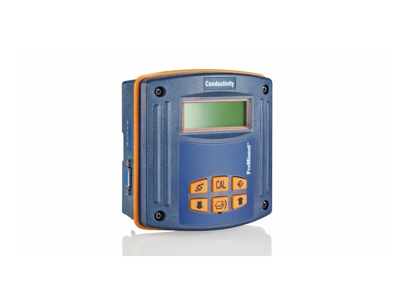
Getting an analyzer 4-20mA to PLC connection right comes down to a few choices. An analyzer 4-20mA to PLC loop gives one value per pair of wires and is simple and dependable. Modbus RTU over RS485 lets one bus carry many values plus alarms and diagnostics. Small systems with one or two measurements are fine on analog alone. Larger ones often use both: analog for control, Modbus for status. Most field problems are not about that choice, though. They come from mixing up 2-wire and 4-wire devices, skipping isolation, or grounding the shield in the wrong place. This article covers the instrument side only.
Analyzer 4-20mA to PLC: 2-Wire or 4-Wire?
A 2-wire (loop-powered) transmitter has no separate supply. The PLC analog input card, or an external 24 V DC source, powers it through the same two wires, and the transmitter regulates the current between 4 and 20 mA. The ProMinent DULCOMETER DMTa is a 2-wire transmitter of this type. It converts pH, ORP, temperature, chlorine and conductivity sensor signals into 4-20 mA and can be powered directly from a 2-wire PLC analog input.
A 4-wire device has its own power, mains or 24 V DC, and two more wires carry an active 4-20 mA output. Most panel analyzers with a display and most colorimetric analyzers work this way.
The classic mistake is connecting an active 4-wire output to an active PLC input. Two sources fight, the reading sits at zero or full scale, and the card can be damaged. Check whether the input card is sourcing or sinking, check the analyzer output type, and remember: one power source per loop.
Why Analyzer Signal Wiring Needs Isolation
Sensors sit in water, and water is effectively connected to earth. The PLC is grounded too, so every analyzer 4-20mA to PLC loop in a wet process is exposed. Any potential difference between those two points pushes noise into the loop. You see slow drift or periodic jumps, worst on high-impedance pH signals.
The fix is galvanic isolation. An analyzer with an isolated output is ideal. The DMTa, for example, isolates the sensor input from the measured value output. Otherwise add a signal isolator in front of the PLC. Isolators and loop power supplies are listed under isolators and barriers.
Shields and Cable Routing
Use twisted, shielded pair cable for each analyzer 4-20mA to PLC run. Ground the shield at one end only, normally the control panel end. Grounding both ends creates ground loops. Keep signal cables out of trays carrying VFD and motor power. If they must share, use a divider and cross at right angles.
For long runs of pH or ORP, convert to 4-20 mA close to the sensor. The DULCOMETER 4-20 mA signal converter mounts directly on the sensor for exactly this reason: millivolt signals do not travel well.
Scaling the Analyzer 4-20mA to PLC Range
4 mA is the bottom of range and 20 mA the top, and both ends must match in the analyzer and the PLC. A common error is changing the range on the analyzer but not in the PLC, so the HMI disagrees with the local display. During commissioning, use the analyzer's output simulation (or a current source) to inject 4, 12 and 20 mA into the analyzer 4-20mA to PLC loop and confirm the PLC reads correctly.
Currents below 4 mA or above 20 mA can flag a broken wire or a fault. Configure these as alarms and drive the dosing loop to a safe state rather than trusting a bad value.
Water Quality Instrument Modbus, RS485 and HART
For water quality instrument Modbus links, RS485 with Modbus RTU is the norm. Match the slave address, baud rate, parity and stop bits, then the register map and data format: integer or float, and byte order. Fit termination resistors at both ends and wire the bus as a daisy chain, not a star. If the PLC has no RS485 port, a protocol gateway can convert to Ethernet.
HART puts a digital signal on top of the 4-20 mA loop. The analog value still flows, and you can read diagnostics and change settings. It makes sense if the site already uses HART handhelds or asset management software.
Make a Point List Before You Wire
Before anyone pulls cable for an analyzer 4-20mA to PLC job, agree a simple point list between electrical and controls. For each instrument record:
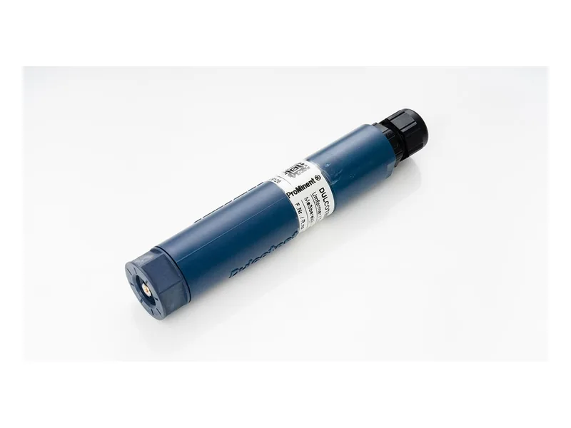
Figure 1: ProMinent DULCOMETER 4-20 mA signal converter. Image source: ProMinent official website
- Tag, parameter, range and units.
- Signal type (2-wire, 4-wire or Modbus) and power source.
- PLC channel, slave address or register.
- Alarm limits and the safe action on fault.
It saves hours during commissioning and makes future replacements easy.
Using the Signal to Drive a Metering Pump
Once the analyzer 4-20mA to PLC signal arrives, a PID block usually outputs 4-20 mA or pulses to the metering pump. From the instrument side: filter the measured value a little so the pump does not chase noise; let the PLC freeze output or switch to manual while an analyzer is in calibration or fault; and for critical dosing points, alarm in both software and hardware. Pump-side signal choices are covered in 4-20mA vs pulse vs RS485 for metering pumps, and the full loop in pH and chlorine analyzers linked to dosing pumps.
Always isolate power and confirm the panel is dead before touching terminals.
Conclusion
When you take an analyzer 4-20mA to PLC, analog gives stability and Modbus gives breadth, and many plants use both. On site, watch three things: do not mix up 2-wire and 4-wire, isolate the signal, and ground the shield at one end. Transmitters and controllers are on our ProMinent brand page. Send your analyzer model, PLC model and point list, and contact our engineers to check the wiring.
FAQ
Why does my analyzer 4-20mA to PLC reading keep jumping?
Usually grounding or noise. Check whether the shield is grounded at both ends and whether signal and power cables share a tray, then add an isolator.
Can a 2-wire transmitter connect to a passive PLC input?
Yes, but you need an external 24 V DC supply in series with the loop.
Modbus values look nonsensical. What now?
Check the register address and data format. Wrong byte order on floats gives wild numbers.
One analyzer, two parameters: do I need two cable pairs?
With analog, yes, one output per value. With Modbus, one bus reads everything.
Will calibrating the analyzer upset the dosing pump on an analyzer 4-20mA to PLC loop?
It can. Set a calibration hold in the PLC so output freezes or switches to manual during the procedure.