
Plunger Metering Pump Control: Stroke Actuators, VFDs and Signals
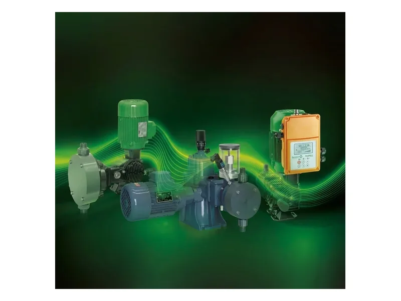
Plunger metering pump control comes down to two variables: how far the plunger travels on each stroke, and how many strokes it makes per minute. Flow is roughly plunger area times stroke length times stroke rate, and since plunger area is fixed at purchase, every control method works on the other two.
This article is for control engineers and plant maintenance teams who need to automate a packed plunger pump. We cover the adjustment mechanism, the main control components, and how actuators and drives fit into a PLC loop. For the pumping cycle itself, see how a plunger metering pump works.
The Stroke Length Mechanism Behind Plunger Metering Pump Control
The motor drives a worm gear, which turns an eccentric or crank. The adjustment mechanism changes the effective eccentricity, so the plunger travels anywhere from zero to full stroke. On many designs a handwheel moves a slide through a lead screw, and the slide position sets where the return stroke begins. A dial, sometimes with a vernier, shows the setting.
Doseuro's PDP series A-I plunger pumps are a good reference. They use an internal worm gear in an oil bath, stroke can be adjusted with the pump at rest or running, and adjustment can be manual or automatic through an actuator driven by 4-20 mA, fieldbus or air. Doseuro rates accuracy at plus or minus 1% within 10 to 100% of rated capacity.
Check the manual before adjusting a stopped pump. Some designs only allow stroke changes while running, and forcing the handwheel at standstill can damage the mechanism.
Plunger Metering Pump Control Components
A fully automated pump usually carries some or all of these parts:
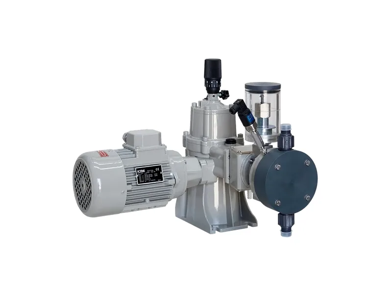
Figure 1: Doseuro PDP positive return plunger unit. Image source: Doseuro official website
- A stroke handwheel, or an electric stroke actuator in its place
- A motor and variable frequency drive for stroke rate
- Position feedback from the actuator, typically a 4-20 mA output
- Liquid end protection such as a relief valve, pressure gauge and packing leak detection
- A local control station for hand/auto selection and emergency stop
Small skids may have only a handwheel and a start button. Large chemical injection packages often have everything, including remote communication.
Two Routes to Automatic Plunger Metering Pump Control
Electric stroke actuator
The actuator replaces the handwheel and turns the lead screw to match a 4-20 mA command. The motor keeps running at rated speed, so cooling and torque are never an issue, and flow tracks the signal in a fairly linear way. The weakness is speed. A full travel takes a while, so it cannot follow fast process swings.
Variable frequency drive
A VFD changes motor speed and therefore stroke rate. It responds quickly and is easy to retrofit. At low frequency, however, the shaft fan slows down and motor cooling drops, so usable turndown depends on the motor. Motors with a separate cooling fan can run slower.
Many plants combine the two. The actuator sets stroke length for the recipe or season, and the VFD trims flow in real time. Step-by-step tuning of that combination is covered in our guide to plunger pump stroke adjustment with frequency control.
Wiring Plunger Metering Pump Control into a PLC
There are three common signal types: 4-20 mA analog, pulse, and RS485 or fieldbus. Our comparison of 4-20 mA vs pulse control explains how to choose.
The usual strategy is flow pacing. A main line flow meter feeds the PLC, which calculates the dose and converts it to a stroke or speed command. Where tighter control is needed, a trim loop adjusts the dose based on pH, ORP or residual chlorine.
Mistakes we see in the field:
- No signal priority. Both actuator and VFD follow live PLC commands, the two loops fight, and flow hunts. Generally one should be held fixed while the other trims, and the PLC logic should say so in writing.
- Feedback left unwired. The PLC sends commands but never checks actual position, so a stuck actuator goes unnoticed.
- Running at very short stroke for long periods. Packing leakage becomes a larger share of output and accuracy suffers. Keep normal flow in the middle of the range where possible.
Choosing a Plunger Metering Pump Control Scheme
Start your plunger metering pump control choice with how fast the process changes. A steady flow needs only a handwheel and regular calibration. Batch or recipe changes suit an electric actuator. A main flow that varies minute to minute calls for a VFD, or both devices together. Then confirm area classification, because the actuator and motor both need suitable explosion protection in hazardous zones. You can browse models in our plunger metering pump range or the Doseuro brand page.
Commissioning Checks for Plunger Metering Pump Control
Before handing the loop to operations, run a few checks. Drive the actuator from 4 mA to 20 mA and confirm the feedback follows across the full span. Record actual flow at around 25, 50 and 75% stroke so the PLC uses a real curve rather than the nameplate line. Test what the pump does on signal loss. Finally, verify that hand mode at the local station overrides remote commands, because plunger metering pump control that cannot be taken back locally is a maintenance hazard. A short commissioning record like this makes later plunger metering pump control troubleshooting much faster, and it gives operators a baseline when plunger metering pump control drifts.
Conclusion
Plunger metering pump control is simple in principle. Stroke length sets volume per stroke, motor speed sets stroke rate, and an actuator or VFD hands each variable to the PLC. Use manual adjustment for steady duty, an actuator for recipe changes, and a VFD for fast swings, with a clear rule for which device leads. Share your flow range, pressure, fluid and signal type, and contact our engineers to put the control package together.
FAQ
Can I adjust stroke length while the pump is running?
Usually yes, but follow the manufacturer. Some pumps allow adjustment at rest, others require the pump to be running.
What if the electric actuator fails?
Most actuators allow manual override or can be removed to restore the handwheel. Run in manual until the actuator is repaired.
What happens if the 4-20 mA signal is lost?
It depends on configuration. Typical options are hold last position, go to zero, or alarm and stop; for strong acids and caustics, alarm is the safer choice.
Is it a problem to run the VFD at very low frequency?
It can be. Motor cooling and torque both drop, so long low-speed operation needs an inverter-duty motor or a separate fan.
Flow does not match the setting after adjustment. What now?
Calibrate. Measure actual flow with a calibration column or by weight, then correct the setting curve; depressurize the line before opening the liquid end.